This website uses cookies to improve your experience while you navigate through the website. Out of these cookies, the cookies that are categorized as necessary are stored on your browser as they are essential for the working of basic functionalities of the website. We also use third-party cookies that help us analyze and understand how you use this website. These cookies will be stored in your browser only with your consent. You also have the option to opt-out of these cookies. But opting out of some of these cookies may have an effect on your browsing experience.
Installation Instructions: Density Line Engine Mounts for B8 Audi A4/S4, A5/S5, Q5/SQ5
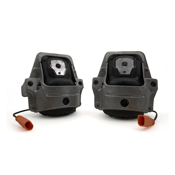
Motor Mount, Street Density Line, B8 Audi A4/S4, A5/S5, Q5/SQ5
The installation of your 034Motorsport Street Density Engine Mounts for the B8 Audi A4/S4, A5/S5, Q5/SQ5 is an involved process that will take an experienced mechanic approximately 4-5 hours to complete. These installation instructions were written for a B8 Audi S4 (installation for other models is similar) to supplement the factory installation procedure, which is outlined here.
Supplied Parts:
- 034Motorsport Street Density Engine Mounts
Tools Needed:
- Breaker Bar for Engine Mount Bolts
- Ratchet
- 6” & 12” Extensions
- T-27 Torx
- Phillips Screwdriver
- 18mm Socket
- 16mm Socket
- 13mm Socket
- 10mm Socket
- 8mm Triple Square
- Engine Hoist or Jack to Support Engine
Step 0 – Raise the vehicle securely on jackstands, ramps, or a lift, in order to gain access to the undercarriage. Make sure you have all tools necessary for installation of the new mounts.
Step 1 – Remove the front wheels.
Step 2 – Remove the front axle shields and unbolt the fender liners so that you can pull them back as pictured below.

Step 3 – Support the engine securely using a hoist, support, or jack.

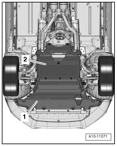
Step 4 – Remove the factory noise insulation.

Step 5 – From here, you can either follow the factory procedure and replace one side at a time, or opt to lower the entire subframe and replace both mounts at the same time. Lowering the entire subframe requires the removal of more hardware, but may provide for easier access to the engine mounts. Lowering the subframe is highlighted below.
Step 6 – Disconnect the connectors circled in red, and remove the nut/bracket holding the N145 harness to the subframe.

Step 7 – Securely support both sides of the subframe as pictured below, making sure you can lower it as needed to access the engine mounts. Please note that DSG vehicles may require you to disconnect additional lines or hoses.

Step 8 – Disconnect the front sway bar end links from the sway bar.

Step 9 – Remove the rear subframe bolts on both sides. You may have to disconnect the steering column from the steering rack to lower the subframe enough to remove your mounts.
Step 10 – Remove the front subframe bolts on both sides, as well as the bolt going through the engine mount into the engine mount arm. These are circled in red below.

Step 11 – Lower the subframe slowly, just enough to gain access to the engine mounts for removal. This should be approximately 25mm - 35mm. Take care to ensure that no wires or lines are snagged, pulled, pinched, or otherwise damaged when lowering the subframe!
Step 12 – Remove the bolts attaching the engine mounts to the subframe, as pictured below.

Step 13 – Remove the 8mm triple square bolts securing each of the engine mount retaining plates.

Step 14 – Remove the engine mount retaining plates.

Step 15 – Remove the factory engine mounts.

Step 16 – Installation of your 034Motorsport Street Density Engine Mounts is the reverse of removal. If your car is equipped with factory active mounts, please make sure to connect the N145 connectors to the plugs on your 034Motorsport Street Density Engine Mounts. The subframe to engine mount bolts go through the holes labaled with "6" on V6 cars, and the holes labeled with "4" on 4-cylinder cars.
Tightening Specifications: Refer to Subframe & Engine Mount Overview & Tightening Specifications.
Factory Engine Mount Replacement Procedure
Special Tools, Testers, and Auxiliary Items Required
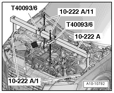
- Engine Support Bridge (10 - 222 A)
- Spindles (10 - 222 A /11)
- Engine Support Supplement Set (T40093)
- Adapter (T40093/6)
- Oil Collecting and Extracting Device
Right Engine Mount
To avoid repeat repairs, do the following if the engine mount is faulty:
- Replace the faulty engine mount and its retaining plate.
- Likewise replace the engine mount on the opposite side, check the retaining plate and replace it if necessary.
Removal
- Install the (10 - 222 A) with one on the left and right strut towers, as shown in the illustration.
- Attach the (10 - 222 A /11) to the left and right engine lifting eyes.
- Lightly tension the engine with spindles.
- Remove the right front wheel.
- Remove the right front wheel housing liner.
- Remove the noise insulation (1 and 2).
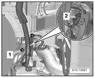
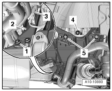
- Remove and disconnect the connector (2) on the right electrohydraulic engine mount solenoid valve (N145).
- Remove the nut (1) and remove the bracket with the wiring harness from the subframe.
- Remove the bolts (1, 2 and 4) and move the right engine mount retaining plate (3) to the side.
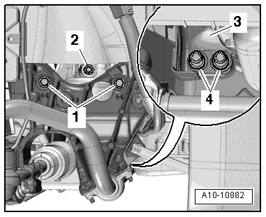
Vehicles with S-Tronic Transmission 0B5
- Remove bolt (arrow) on ATF line bracket.

All Vehicles
- Lift the engine by the right (10 - 222 A /11) (1) by approximately 20 mm.
- Remove the right engine mount.
Installation
Install in reverse order of removal. Note the following:
Tightening Specifications: Refer to Subframe & Engine Mount Overview & Tightening Specifications.
Vehicles with S-Tronic Transmission 0B5
- Install ATF lines.
All Vehicles
- Install the front wheel housing liner and noise insulation.
- Install the front wheel.
Left Engine Mount
To avoid repeat repairs, do the following if the engine mount is faulty:
- Replace the faulty engine mount and its retaining plate.
- Likewise replace the engine mount on the opposite side, check the retaining plate and replace it if necessary.
Removal
- Install the (10 - 222 A) with one on the left and right strut towers, as shown in the illustration.
- Attach the (10 - 222 A /11) to the left and right engine lifting eyes.
- Lightly tension the engine with spindles.
- Remove the left front wheel.
- Remove the left front wheel housing liner.
- Remove the noise insulation (1 and 2).
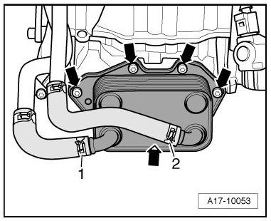
- Remove the bolts (arrows) and move oil cooler to the side with the coolant hoses (1 and 2) still connected.
Vehicles with an After-Run Coolant Pump (V51)
- Remove the after-run coolant pump and the oil cooler.
All Vehicles
- Remove Air Conditioning (A/C) compressor.

Vehicles with Hydraulic Power Steering
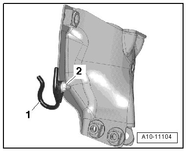
- Remove the nut (2) and free up the bracket (1).
All Vehicles
- Remove the left subframe bolt (2).
- The left subframe bolts (1 and 3) and all the right subframe bolts remain installed.
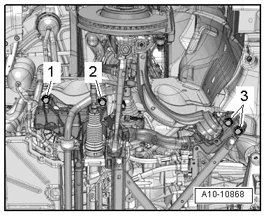
- Disconnect the connector (3) on the left electrohydraulic engine mount solenoid valve (N144).
- Remove the left engine mount bolts (1, 4 and 5).
- Move the left engine mount retaining plate (2) to the side.
- Remove the left engine mount.
Installation
Install in reverse order of removal. Note the following:
Tightening Specifications: Refer to Subframe & Engine Mount Overview & Tightening Specifications.
All Vehicles
- Tighten the subframe.
- Install A/C compressor.
- Install the oil cooler.
- Install the noise insulation.
Subframe & Engine Mount Overview & Tightening Specifications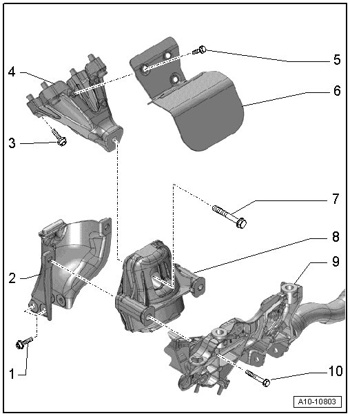
- 1 Bolt - 20 Nm
- 2 Mounting Plate for Engine Mount
- 3 Bolt - 40 Nm
- 4 Engine Support
- 5 Bolt - 10 Nm
- 6 Heat Shield
- 7 Bolt - 90 Nm
- 8 Engine Mount
- 9 Subframe
- 10 Bolt - 55 Nm
Power Steering Fluid Hose Bracket for Vehicles with Hydraulic Power Steering - Tightening Specification
- 2 Nut - 9 Nm